Getting Started in Wokwi
- Skylar Castator
- Feb 10, 2024
- 6 min read
Updated: Feb 12, 2024
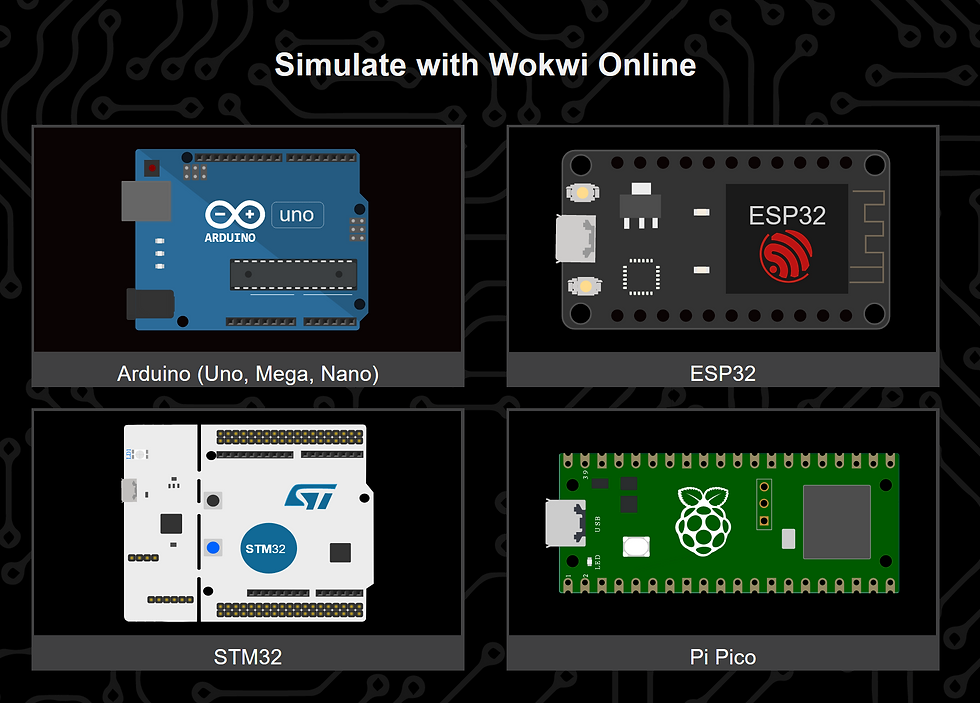
Wokwi is a user-friendly website that allows the user to simulate circuits in their browser. It's a great place to learn and prototype in a cheap and fun interface. This tutorial is a basic project to learn how to use Wokwi yourself and to start working with your own circuits!
Introduction
I first discovered Wokwi from one of my friends on Discord. He had just found the website and was using it to see different example components linked to an Arduino device. I found the servo animations compelling and wanted to make an example of my own. So without delay let's go to the website and start testing things out.
Getting Started

Wokwi has a straightforward interface that allows the user to try out different components and simulate the devices in your browser. They provide several different examples to start with and example code to manage the electronic components in the system. They have made the system very easy for people just starting to learn circuitry and even simplified some wiring to make the examples more understandable versus the rats-nest that happens when designing circuits.
So let's jump into creating an example project. In my example, I'm going to start with a very basic circuit to control an LED device the classic 'Hello World' of Arduino projects and once we have the basics down I will demonstrate a more sophisticated project simulating controlling several stepper motors at once similar to how you would calibrate a 3d Printer.
Hello World
Our first example project will demonstrate connecting an LED to Arduino and turning it on and off with interrupts. If you haven't seen interrupts before, they act as an event handler for Arduino using the GPIO pins 2 and 3. They wait for the digital pin to go from low to high and then activate the event listed as part of the interrupt initialization line.
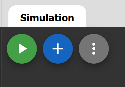
We can start the circuit by using the add button to include the electrical components for the LED, Resistor, and Button.

Once they have been added to the schematic, we can connect a wire from the Arduino 13 pin to the resistor and then connect a wire from the resistor to the LED's anode connection.

#define LED_PIN 13
#define BUTTON_PIN 2

volatile byte state = LOW;

void setup() {
  Serial.begin(9600);
  pinMode(LED_PIN, OUTPUT);
  pinMode(BUTTON_PIN, INPUT_PULLUP);
  attachInterrupt(digitalPinToInterrupt(BUTTON_PIN), blink, CHANGE);
}

void blink(){
  state = !state;
}

void loop() {
  digitalWrite(LED_PIN, state);
}
Stepper Motor Project
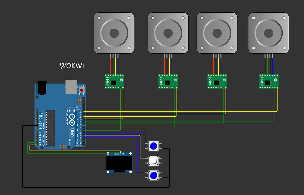
In the next example, we want to demonstrate the use of electromechanical devices. What we will use in this example are stepper motors that are similar to the NEMA 17 found in 3d printers. We will attach each of the stepper motors to a stepper motor driver and then finally we will control them all using an LCD screen.
Setting up the Stepper Motors and Driver
Using Wokwi, you can find information for components by clicking the '?' button when you select the electrical component.
The link can be found below:
We also want to connect Stepper motor drivers to our circuit. These components allow us to control the stepper drivers more efficiently and use fewer pins. The stepper drivers can control the direction of the motors, the speed, and much more. The example page for the A4988 components can be found below.
One of the things you might have noticed using the stepper drivers in Wokwi is that the interface manages the connections for the GND and VCC for you. This simplifies the circuit for you when you are prototyping but once you move to the actual devices themselves, you need to compensate.
The Full Project
The Example project can be found at the link below: https://wokwi.com/projects/389281223437222913
So first we want to include the different libraries we are going to use in this example. We will be including libraries for the stepper driver controllers, the LCD screen, and one for the buttons to control the LCD screen. These libraries will need to be added to the Wokwi interface using the 'Library Manager' tab.
Next, we are going to create variables to manage the number of pins for each button and then link them to the Bounce library we included above.
byte button_pins[] = {3, 4, 5}; // button pins, 3,5 = up/down, 4 = select
#define NUMBUTTONS sizeof(button_pins)
Bounce * buttons = new Bounce[NUMBUTTONS];
The stepper motors also need to be assigned pins and need to be connected to their controller library. This is done by creating AccelSteeper objects and referencing the pins of the controller to the stepper drivers. We also make references to the current motor selected and the position of all the stepper motors to be easily changed later.
const int m1StepPin = 6;
const int m2StepPin = 7;
const int m3StepPin = 8;
const int m4StepPin = 9;
const int m1DirPin = 10;
const int m2DirPin = 11;
const int m3DirPin = 12;
const int m4DirPin = 13;

#define motorInterfaceType 1

//Initializes the Stepper Drivers
AccelStepper stepM1(motorInterfaceType, m1StepPin, m1DirPin);
AccelStepper stepM2(motorInterfaceType, m2StepPin, m2DirPin);
AccelStepper stepM3(motorInterfaceType, m3StepPin, m3DirPin);
AccelStepper stepM4(motorInterfaceType, m4StepPin, m4DirPin);

int selectedMotor = -1;
const int stepsPerRevolution = 200;
int m1StepPos = 0;
int m2StepPos = 0;
int m3StepPos = 0;
int m4StepPos = 0;
The last thing we have to reference before we start initializing the circuit board's process is the code for the screen and the available menus to be displayed on the LCD screen.
U8X8_SSD1306_128X64_NONAME_HW_I2C display(U8X8_PIN_NONE);

int mainMenuLength = 5;
char *menu[5] = {"Main Menu", "X Axis", "Y Axis", "Z Axis", "Extruder"};

int stepperMenuLength = 6;
char *moveStepperMenu[6] = {"Stepper Motor", "-10 mm", "-1 mm", "1 mm", "10 mm", "back"};

int cursor=1;

int currentMenuLen = 0;
int currentMenu = 0;
Now we can start doing the setup of the program we are going to set the parameters of the stepper controllers. This manages the speed acceleration and deceleration of the stepper motors linked to the stepper drivers. We will also initialize the buttons and the LCD to be used within our circuit.
void setup() {
  //Initalizes and sets up the controllers for each stepper driver
  stepM1.setMaxSpeed(1000);
  stepM1.setAcceleration(50);
  stepM1.setSpeed(200);
  stepM2.setMaxSpeed(1000);
  stepM2.setAcceleration(50);
  stepM2.setSpeed(200);
  stepM3.setMaxSpeed(1000);
  stepM3.setAcceleration(50);
  stepM3.setSpeed(200);
  stepM4.setMaxSpeed(1000);
  stepM4.setAcceleration(50);
  stepM4.setSpeed(200);

  //Next we attach all of the buttons to the circuit board
  for (int i=0; i<NUMBUTTONS; i++) {
    buttons[i].attach( button_pins[i], INPUT_PULLUP); // setup the bounce instance for the current button
    buttons[i].interval(25); // interval in ms
  }

  //Setup for the LCD screen
  display.begin();
  display.setPowerSave(0);
  display.setFont(u8x8_font_pxplusibmcgathin_f);

  showMainMenu();
}
This function creates the main menu for the LCD. This menu will allow the user to select a motor to control.
void showMainMenu() {
  cursor=1;
  display.clearDisplay();
  for (int i = 0; i<mainMenuLength; i++) {
    display.drawString(2,i,menu[i]);
  }
  currentMenu = 0;
  currentMenuLen = mainMenuLength;
  display.setCursor(0,1);
  display.print('>');
}
This function is used to create a menu to control the selected stepper motor using the moveStepperMenu options.
void showStepperMenu() {
  cursor=1;
  display.clearDisplay();
  for (int i = 0; i<stepperMenuLength; i++) {
    display.drawString(2,i,moveStepperMenu[i]);
  }
  currentMenu = 1;
  currentMenuLen = stepperMenuLength;
  display.setCursor(0,1);
  display.print('>');
}
This function is the main loop. We check for the button states and move around the menu if one of the buttons was clicked. The select button can either select the stepper motor and then place us into the stepper driver's menu. If the current menu is the stepper driver menu, then it allows us to select a movement amount to rotate the stepper driver.
void loop() {
  for (int i = 0; i<NUMBUTTONS; i++) {
    buttons[i].update(); // Update the Bounce instance
    if ( buttons[i].fell() ) { // If it fell
      if (i==1) { // select
         display.clearLine(7);
         display.setCursor(0,7);
         if (currentMenu == 0)
         {
          selectedMotor=cursor;
          moveStepperMenu[0] = menu[cursor];
          showStepperMenu();
         }
         else{
          executeChoice(cursor);
         }
      }
      else {
        // erase previous cursor:
        display.setCursor(0,cursor);
        display.print(' ');
        if (i==0) { // up
          cursor++;
          if (cursor>(currentMenuLen-1)) cursor=1;
        }
        else { // down
          cursor--;
          if (cursor<1) cursor=(currentMenuLen-1);
        }
        // show cursor at new line:
        display.setCursor(0,cursor);
        display.print('>');
      }
    }
  }

  stepM1.run();
  stepM2.run();
  stepM3.run();
  stepM4.run();
}
Once a stepper motor is selected the user can select a choice within the stepper driver menu to move a certain amount. The function below takes the input of that choice and then provides the stepper driver with the movement amount.
void executeChoice(int choice){
    switch(choice) {
      case 1 :
                moveStepperMotor(-10);
                break;
      case 2 :
                moveStepperMotor(-1);
                break;
      case 3 :
                moveStepperMotor(1);
                break;
      case 4 :
                moveStepperMotor(10);
                break;
      case 5 :
                showMainMenu();
                break;
      default :
                Serial.print("This menu item should not work");
                break;
  }
}
Finally, this function figures out which stepper driver is selected and then applies the difference of the movement to the current stepper driver and moves the stepper motor to the selected position.
void moveStepperMotor(int movementAmount){
  switch (selectedMotor){
    case 1 :
      m1StepPos += movementAmount;
      stepM1.moveTo(m1StepPos);
      break;
    case 2 :
      m2StepPos += movementAmount;
      stepM2.moveTo(m2StepPos);
      break;
    case 3 :
      m3StepPos += movementAmount;
      stepM3.moveTo(m3StepPos);
      break;
    case 4 :
      m4StepPos += movementAmount;
      stepM4.moveTo(m4StepPos);
      break;
  }
}
Conclusion
Using Wokwi to learn electronics is fun and cheap. The cost of buying the stepper motors much less the Arduino board for this example project would have cost me over $100 and as a way to prototype different ideas, I would highly recommend before needing to buy all the hardware yourself. One of the things I still haven't tested out is adding chips to the UI interface. You can find more information in the link below. https://docs.wokwi.com/chips-api/getting-started As I continue making more circuit boards and projects, I plan to use their service more often. It comes down to ease of access and I believe Wokwi does a fantastic job for the user to get prototyping right out of the gate. Feel free to reach out if you have any questions and have fun hacking!