Basic Autonomous Vehicle Robot
- Skylar Castator
- Jan 26, 2024
- 6 min read
Updated: Jan 27, 2024

Introduction
Early in my career, I learned how to make simple robots when I worked for the company Sphero. Over time, I've made a few different projects but never really posted too much about them. Over the holidays, I built this simple robot to start working more with control systems. As part of this learning process, I decided to post the exploration of the subject.
The goals I had for creating this robot included:
Creating hardware and software that can communicate with apps and computers.
Prototype and show the process of connecting the electronics in the robot. Making my circuit boards will come in time, but need to be better at documenting the journey.
The process this tutorial will make is it will break down the circuitry, the code, and how the component works. Once all of the components have been tested and identified, we are going to put it all together into a single project. Divide and conquer is always the best procedure for tackling these projects. It's always worth testing each component properly and understanding how each device works in the larger scheme.
Electronics
The electronics start with the Arduino, I'm using an older version of the UNO.
Parts:
The Chassis

What I started with was using this pre-made chassis that I could buy on Amazon.
The construction is very simple and all you need to do is place on the motors, wheels and a battery pack to get started. We will replace the batteries later on, but this is a good solution to start with.
The next step is starting to mount some of the electronics to the chassis. Specifically the encoders. There are already holes drilled for them and they can align up to the wheels shown in the pictures below.


Motor Control System
The L293D data sheet shows the component pins as seen below. The h bridge helps to be able to reverse the polarity of the motors as well as the ability to stop the motors movements. The link below describes more of the ins and out of the component: https://www.modularcircuits.com/blog/articles/h-bridge-secrets/h-bridges-the-basics/

Let's link up the H bridge, and motors to the Arduino and get some basic code running. The circuit below was the initial way I linked up the H-bridge. You can see pins 5-10 control the 'enable' pins as well as the direction of flow in the circuit.

This is what it looks like on the robot. I used a mini breadboard to run the circuit. You can use whatever board you would like I would just advise not to stick anything down until you know the placement of the remaining components.

Once we link up the circuit, the process of coding firmware for the circuit is simple.
#define ENABLE_A 5
#define MOTOR_A1 6
#define MOTOR_A2 7
#define ENABLE_B 8
#define MOTOR_B1 9
#define MOTOR_B2 10

void driveForward()
{
  Serial.println("Motion Forward");
  digitalWrite (MOTOR_A1, LOW);
  digitalWrite (MOTOR_A2, HIGH);
  digitalWrite(MOTOR_B1, LOW);
  digitalWrite(MOTOR_B2, HIGH);
}

void driveReverse()
{
  Serial.println("Motion Reverse");
  digitalWrite (MOTOR_A1, HIGH);
  digitalWrite (MOTOR_A2, LOW);
  digitalWrite(MOTOR_B1, HIGH);
  digitalWrite(MOTOR_B2, LOW);
}

void setup()
{
  Serial.begin(9600);

  pinMode (ENABLE_A, OUTPUT);
  pinMode (MOTOR_A1, OUTPUT);
  pinMode (MOTOR_A2, OUTPUT);

  pinMode (ENABLE_B, OUTPUT);
  pinMode (MOTOR_B1, OUTPUT);
  pinMode (MOTOR_B2, OUTPUT);
}

void loop()
{
  Serial.println("EnableMotors");
  digitalWrite(ENABLE_A, HIGH);
  digitalWrite(ENABLE_B, HIGH);

  driveForward();
  delay(3000);

  driveReverse();
  delay(3000);

  Serial.println("Stop Motors");
  digitalWrite(ENABLE_A, LOW);
  digitalWrite(ENABLE_B, LOW);
  delay(3000);

}
The next step we want to include now we have the motors working, are the encoders. This helps us determine the amount of space covered by the motors. The encoders use the inner wheel component that has the holes in outer rim. What happens is each time the light is sent through this hole, the encoders activate an interrupt signal to the circuit board, and that then tells the board it's done part of a rotation. We list the number of holes in a rotation and then by counting the interrupts, we can predict the the number of rotations the wheel has made over a period of time.

This example code to run the motors and then use the encoders to get the RPM of the wheels driving. Mind this example does not track the direction of the motors to change the RPM.
#include "TimerOne.h"
#define ENCODER_LEFT_PIN 2
#define ENCODER_RIGHT_PIN 3
#define ENCODER_N 20

#define ENABLE_A 5
#define MOTOR_A1 6
#define MOTOR_A2 7
#define ENABLE_B 8
#define MOTOR_B1 9
#define MOTOR_B2 10


unsigned int counter1 = 0;
unsigned int counter2 = 0;
float leftRPM = 0;
float rightRPM = 0;

void setupEncoders()
{
  pinMode(ENCODER_LEFT_PIN, INPUT);
  pinMode(ENCODER_RIGHT_PIN, INPUT);

  Timer1.initialize(1000000); // set timer for 1 sec
  attachInterrupt(digitalPinToInterrupt(ENCODER_LEFT_PIN), inturruptEncoder1, RISING);
  attachInterrupt(digitalPinToInterrupt(ENCODER_RIGHT_PIN), inturruptEncoder2, RISING);
  Timer1.attachInterrupt(interuptTimerOne);
}

void inturruptEncoder1()
{
  counter1++;
}

void inturruptEncoder2()
{
  counter2++;
}

void interuptTimerOne()
{
  Timer1.detachInterrupt();
  Serial.print("Counter  1 : ");
  Serial.println(counter1);
  Serial.print("Counter  2 : ");
  Serial.println(counter2);

  leftRPM = (60.00) * (float(counter1) / float(ENCODER_N));
  rightRPM = (60.00) * (float(counter2) / float(ENCODER_N));
  Serial.print("Motor Left RPM : ");
  Serial.println(leftRPM);

  Serial.print("Motor Right RPM : ");
  Serial.println(rightRPM);
  counter1 = 0;
  counter2 = 0;
  Timer1.attachInterrupt(interuptTimerOne);
}

void driveForward()
{
  Serial.println("Motion Forward");
  digitalWrite (MOTOR_A1, LOW);
  digitalWrite (MOTOR_A2, HIGH);
  digitalWrite(MOTOR_B1, LOW);
  digitalWrite(MOTOR_B2, HIGH);
}

void driveReverse()
{
  Serial.println("Motion Reverse");
  digitalWrite (MOTOR_A1, HIGH);
  digitalWrite (MOTOR_A2, LOW);
  digitalWrite(MOTOR_B1, HIGH);
  digitalWrite(MOTOR_B2, LOW);
}

void setup()
{
  Serial.begin(9600);
  setupEncoders();
  pinMode (ENABLE_A, OUTPUT);
  pinMode (MOTOR_A1, OUTPUT);
  pinMode (MOTOR_A2, OUTPUT);

  pinMode (ENABLE_B, OUTPUT);
  pinMode (MOTOR_B1, OUTPUT);
  pinMode (MOTOR_B2, OUTPUT);
}

void loop()
{
  Serial.println("EnableMotors");
  digitalWrite(ENABLE_A, HIGH);
  digitalWrite(ENABLE_B, HIGH);

  driveForward();
  delay(3000);

  driveReverse();
  delay(3000);

  Serial.println("Stop Motors");
  digitalWrite(ENABLE_A, LOW);
  digitalWrite(ENABLE_B, LOW);
  delay(3000);

}
Distance Sensor

The next piece we will add to the system is the distance sensor.
#define TRIGGER 12
#define ECHO 13

void setup() {
  Serial.begin(9600);
  pinMode(ECHO, INPUT);
  pinMode(TRIGGER, OUTPUT);

}

void loop() {
  int distance = 0;
  int average = 0;

  for (int i = 0; i < 4; i++)
  {
    digitalWrite(TRIGGER, LOW);
    delayMicroseconds(2);

    digitalWrite(TRIGGER,HIGH);
    delayMicroseconds(10);
    digitalWrite(TRIGGER,LOW);

    // Speed of sound is:
    // 13511.811023622 inches per second
    // 13511.811023622/10^6 inches per microsecond
    // 0.013511811 inches per microsecond
    // Taking the reciprocal, we have:
    // 74.00932414 microseconds per inch
    // Below, we convert microseconds to inches by
    // dividing by 74 and then dividing by 2
    // to account for the roundtrip time.
    distance = pulseIn(ECHO_PIN,HIGH);
    distance  = distance /74 /2;
    average += distance;
    delay(10);
  }

  distance = average /4;

  Serial.print("u ");
  Serial.print(distance);
  Serial.print("\n");
  Serial.println(distance);
}
Magnetometer
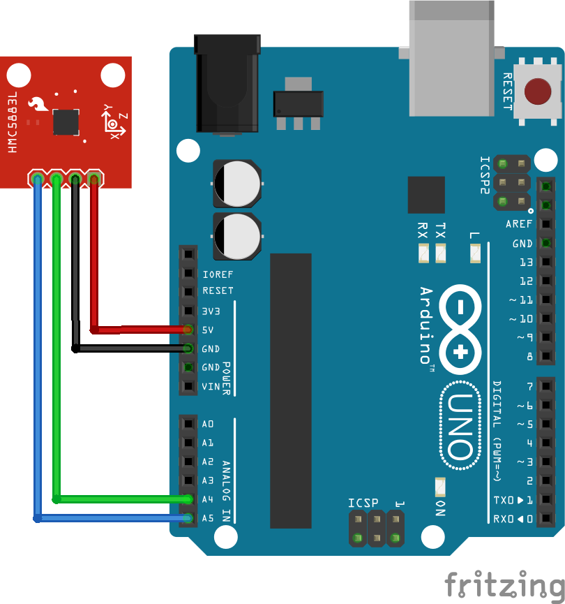
The firmware below uses the QMC5883LCompass library. https://github.com/mprograms/QMC5883LCompass You just want to initialize the compass and use the read call whenever you want to update the magnetometer sensor. The library also uses hard-coded pin references for the sensor as shown above. To understand more about what is going on in the sensor, you can use the link below. https://www.circuitbasics.com/how-to-setup-a-magnetometer-on-the-arduino/
Below is the example firmware to get started getting data.
#include <QMC5883LCompass.h>

QMC5883LCompass compass;

void setup()
{
  Serial.begin(9600);
  compass.init();
}

void loop()
{
  int x, y, z, a, b;
	char directionArray[3];

	compass.read();

	x = compass.getX();
	y = compass.getY();
	z = compass.getZ();

	a = compass.getAzimuth();

	b = compass.getBearing(a);

	compass.getDirection(directionArray, a);

	Serial.print("X: ");
	Serial.print(x);

	Serial.print(" Y: ");
	Serial.print(y);

	Serial.print(" Z: ");
	Serial.print(z);

	Serial.print(" Azimuth: ");
	Serial.print(a);

	Serial.print(" Bearing: ");
	Serial.print(b);

	Serial.print(" Direction: ");
	Serial.print(directionArray[0]);
	Serial.print(directionArray[1]);
	Serial.print(directionArray[2]);

	Serial.println();
  delay(300);
}
Bluetooth

This is the last component we want to add to the circuit. The Bluetooth will connect to the computer or mobile devices. We will be sending communications over the serial ports which can be read from the external device.

To test out the communication you can download the application Serial Bluetooth Terminal. You can search for the device name in your settings, connect it, and then finally read and send serial communications after connecting up the firmware below. A more in-depth tutorial can be found in the link below.
#include <SoftwareSerial.h>

SoftwareSerial EEBlue(2,3); //RX and TX
void setup()
{
  Serial.begin(9600);
  EEBlue.begin(9600);
  Serial.println("The Bluetooth gates are open.");
  Serial.println("Connect to HC-05 with 1234 as key");
}

void loop()
{
  if (EEBlue.available()){
    Serial.write(EEBlue.read());
  }

  if (Serial.available())
  {
    EEBlue.write(Serial.read());
  }
}
Putting It All Together

In this section, the schematic shows all devices connected. We had to move around the Bluetooth pins to give the encoders the interrupt pins, but otherwise, the circuit works with all of the previous steps.
There has also been the process of improving the firmware.
Some of the new features include:
Timers from Arduino instead of delays.
C++ classes to maintain the states of the components and robot.
Communication from the Bluetooth in the JSON format for easier readability.
The link above will have all of the example code for the project. Due to how many files the code is broken up into, it is better to just use the link than to show all the code within this tutorial. In the link, you will also find the Fritzing schematics for each part, the example code, and eventually 3d models used in the chassis.
The program is running below. In this example, it is using a simple process where it looks in front of itself for an object at a certain distance. Once it is close enough to the object, it rotates in a random direction and then drives until it sees the next object. This is not using all the features of the components at the moment, but the goal was to have a bot that can be expanded on.
Conclusion
This is only the beginning. We have set up the components on the circuit board to just a framework in place to do more sophisticated programming. By linking up new devices over Bluetooth, we can connect mobile applications as well as connect this device to the computer to run either ROS or machine learning algorithms.
In future updates, I plan to do the following:
Programming a ROS simulator.
Making a PID or MPC Controller to refine the drive mechanics.
3D models that can be printed and attached to the frame.
The Final bit will be making a circuit board that contains all the components listed for the final robot.